您现在的位置: 晨光科技 >> 文章 >> 技术理论 >> 风力发电 >> 正文  
  THE SAIL DESIGN PROCESS  帆船设计过程         
THE SAIL DESIGN PROCESS  帆船设计过程
[ 作者:佚名    转贴自:http://www.hlmffsailmaker.com/thesaildesignprocess.htm    点击数:160    更新时间:2010/2/25    文章录入:yuanyuan ]
[注:本站登载的某些文章并不代表本站支持或反对其观点或肯定其真实性]

帆的设计过程
三维做模,压力分布,应力图,激光切割,模拟测试和更多的数据做一个现代帆,下面简述提供给你一些帆设计步骤。
第一步是决定适合你帆船的帆的几何图形,需要确定所有外部尺寸。
帆的外部尺寸输入到我们拥有当今最先进的帆设计软件后帆的三维图形就描绘出来了。在大多数情况下,帆是用其表面的水平和垂直截面来描绘帆的三维图形。描述这些截面的关键因数是弦深度,最大拱位置,入口,出口,扭曲。
一旦帆的三维形状确定,接着进行帆的测试,做这个的目标是使帆船的升力与阻力比达到最佳,这些系数随帆的三维形状不同而变化
一旦帆的最佳形状确定,接下来对帆进行有限因数和压力分布进行分析。通过分析得到非常有用的信息,除了考虑帆上的附载还必须考虑材料的属性。分析工作,帆的三维形状模和确切的帆材料完成后,帆分成二维的小片进行切割。

Three dimensional modeling, pressure distribution, stress strain pictorials, laser cutting, wind tunnel testing, and much more all figure into making a modern sail for your boat. The following outline will bring you through some of the steps used in designing sails in the 90 ' s and beyond.  

      The first step in any sail design process is to decide on the geometry of the sail needed to fit the boat. All the outside dimensions need to be defined. In most cases this is an easy operation and can be accomplished by directly measuring the boat with a tape measure or consulting a sail plan which is a scale drawing of the boat. Once the size of the sail is confirmed the interesting analysis starts. 

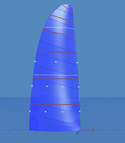
      The outside dimensions of the sail are entered into a sail design program where a 3 dimensional shape is described. In most cases 3-dimensional shapes are described by horizontal and vertical cross sections of the surface. The key factors in describing these sections are chord depth %, maximum draft position, entry and exit angle, and twist ( the amount of deflection the leech has from a straight line between the clew and head, generally described in degrees). For most boats the optimal sail shape cannot be applied to the sails because of several obstacles like genoa track locations, spreader lengths and position, headstay sag and mast bend.

     For example, if a sailmaker designs a genoa for a boat that has long spreaders and does not consider the spreader length when designing the sail it can not achieve the designed 3-dimensional sail shape the genoa must be trimmed through the top spreader to do so. Since the spreader cannot move the sail cannot be trimmed in, and thus the sail sets with more twist than designed. This one little design flaw causes the sail to set with the following problems, flatter camber than designed, fuller entry to the sail in the upper portion thus, the sail luffs earlier and, wider exit angle decreases the power in the sail.  

       Once the 3-dimensional sail shape is described the sail is ready for wind tunnel testing. The goal of wind tunnel testing is to optimize the lift and drag ratios for the boat. These coefficients change with the change in 3-dimensional shape. Therefore several models may be made to hone in on exact specifications.  

      Once an optimum shape is settled upon the sail now enters a purely analytical aspect of the sail design process, finite element analysis and pressure distributions. To get meaningful information from finite element analysis we must consider the properties of the material used to make the sail in addition to the loading on the sail. Since sailcloth is non-isotropic in it stretch resistance we utilize a polar plot of the materials resistance to stretch, and the placement or alignment of this material in the sail. Since sails are dynamic in their use and do not have one load path that handle all conditions and trim. The placement and aligment of the material utilized is an important aspect of the optimization process. Therefore the material selected must have ample strength in all directions to handle the dynamic loading. To help us understand these types of loads we generate stress and strain graphs of the sails. These graphs analyze the sail and allow adjustments to the design or shape of the sail, these adjustments are made to bring the sail into predetermined stress/ strain limits. The output from this process is a loaded 3-D sail shape taking into account initial 3-D shape, material properties and alignment, wind speed and direction. This deformed 3-D shape is then brought back into the design program. 

     Stress: F/A, or the load divided by cross sectional area. 

     Strain: (Li-Lo)/Lo, or Deformation in length divided by original length. 

     Modulus "E" = Stress / Strain, is the slope of the straight line portion of the stress strain diagram..

     Once all the analytical work is completed and the 3-D mold of the sail is decided upon and the exact material is selected, the sail can now be broken down into small 2-D pieces and cut out. This is accomplished mathematically with geodesics. A geodesic is the shortest distance between two points on a curve surface. Similar to a great circle route when crossing and ocean, the same principals apply to the sail surface. The term mold is used in several sail companies. Currently all sails, if designed utilizing a 3-D design program, are mold shapes. No sail material is molded. All sails today are all constructed with flat plates that are shaped to simulate the 3-D shape. The image below illustrates one such panel, the yellow line shows a magnification of the curve used on a panel in a sail. 

  • 上一篇文章: 船帆的设计原理

  • 下一篇文章: 阻力型风力机图片
  •    
    [注:标题搜索比内容搜索快]
    发表评论】【告诉好友】【打印此文】【关闭窗口
     最新5篇热点文章
  • 轨道钢承重计算公式及应用[109]

  • 【选型】如何为变频器选取阻值…[82]

  • AIS2023参展厂商名录[343]

  • AGV综合选型[170]

  • APIE 2023第4届亚太国际智能装…[138]

  •  
     最新5篇推荐文章
  • 外媒:正在唤醒中国的习近平[305]

  • 中国反伪科学运动背后的CIA黑手…[494]

  • [转载]袁隆平真言:中国最大的…[667]

  • 台专家:当年我们造IDF时 大陆…[572]

  • 旅日华人:中国严重误判日本民…[577]

  •  
     相 关 文 章
  • 近看帆船[55]

  • 青岛最贵帆船现身奥帆码头 售价…[96]

  • 帆船航海基础知识[180]

  • 水手造最快帆船形似飞机 欲40天…[135]

  • 船帆的设计原理[235]


  •   网友评论:(只显示最新10条。评论内容只代表网友观点,与本站立场无关!)
        没有任何评论
    设为首页 | 加入收藏 | 联系站长 | 友情链接 | 版权申明 | 管理登录 | 
    版权所有 Copyright© 2003 晨光科技        站长:璀璨星辰        页面执行时间:332.03毫秒
    Powered by:MyPower Ver3.5