Control of tethered airfoils for a new class of wind energy generator
新型风力发电机的固定机翼的控制
M. Canale, L. Fagiano, M. Ippolito, M. Milanese
Abstract―The paper investigates the control of tethered
airfoils in order to devise a new class of wind generators able to
overcome the main limitations of the present aeolian technology
based on wind mills. A model taken from the literature is
used to simulate the dynamic of a kite which can be controlled
by suitably pulling two lines. Energy is generated by a cycle
composed of two phases, indicated as the traction and the
recovery one. The control unit has two electric drives which act
as motors in pulling the lines for controlling the flight or for
recovering the kite and as generators if the kite pulls the lines.
In each phase, control is obtained by “fast” implementations
of suitable NMPC designs. In the traction phase the control
is designed such that the kite pulls the lines, maximizing the
amount of generated energy. When the maximal length of the
lines is reached, the control enters the recovery phase and the
kite is driven to a region where the lines can be pulled by
the motors until the minimal length is reached, spending a
small fraction of the energy generated in the traction phase,
and a new traction phase is undertaken. Simulation results are
presented, related to a recently built small scale prototype.
摘要―风力发电机的机翼的控制的问卷调查已展开,此调查旨在发明一种新的风力发电机,以克服现有的风力发电技术上的不足。从中研发出来的模型按照风筝动力学,似风筝能通过两条线来控制。一个由两阶段组成的循环产生能量,阶段之一是牵引阶段,另一个则为恢复阶段。控制组有两个电力驱动器,像一个发动机牵着绳控制飞行或收回风筝一样,当风筝牵引绳时,控制组又像一个发电机。每一阶段中的控制都是由相应的NMPC(非线性预测控制)设计的快速执行方案实现的。在牵引阶段,控制方法是按照能最大产生电能的标准来设计的。当风筝飞到绳子的最大长度时,控制进入恢复阶段,风筝将被引向一特定区域,在这一区域发动机把绳子拉到其长度的最小限度,此时发电机只有一小部分处于牵引阶段,而新的牵引阶段则在酝酿之中。模拟结果会在新近建造的一个小的模型中体现。
I. INTRODUCTION
I. 介绍
Energy generation has become an urgent, strategic issue at
the global scale. At present, about 80% of world electric
energy is produced from thermal plants making use of fossil
sources (oil, gas, coal). The economical, geopolitical and
environmental problems related to such sources are becoming
every day more and more evident. Nuclear plants have their
own problems related to security aspects and radioactive
waste management. For these reasons it is of primary importance
for the scientific community to explore and support
new renewable energy technologies, able to provide more
efficient solutions than the existing ones to the severe energy
shortage of the planet.
能源发动机已经成为全球范围内的岌待解决且具有战略意义的问题。目前世界约有80%的能源由热能产生。因此全体科研人员最重要的任务就是开发利用新型可循环利用能源,提供能有效解决全球能源急剧短缺问题的方法,这些方法应比现有资源更能效。核电站也有它们自身的不足,比如安全问题和放射性垃圾等. 由于这些原因,对科学团体来说,探索和支持新型可再生能源技术,使之提供比现有的技术更有效地解决地球严重的能源短缺问题,这显得最为重要。
Wind turbines are currently the largest source of electric
power produced with renewable energy (excluding hydro
power plants) [1]. However, they require heavy towers, foundations
and huge blades, which make a significant impact on
the environment, require massive investments and long-term
amortization periods. All these problems reflect in electric
energy production costs that are not yet competitive, in strict
economic sense, with the ones of thermal generators, despite
recent large rises of oil and gas prices. Moreover, wind farms
have wide problems of social acceptance due to their territory
occupation, which is unacceptably higher than for thermal
plants of the same power (up to 200-300 times).
风涡轮当前是可循环能源中最大的发电源(水力发电除外)。然而种设备需要笨重的塔体,厚实的地基及巨大的风叶,所有这些都会对环境带来很在的影响。除此之外它还需要雄厚的资金投入,回收缓慢。尽管最近石油和天然气的价格剧增,从经济角度严格考虑,此发电成本上的所有问题与热能发电设备相比还是没有竞争力的。此外因为占地面积等问题,风涡轮场还有存在社会认可的问题,这一问题比同等发电量的热能发电站存在的更大(多达200-300倍)。
This paper illustrates a first study conducted at Politecnico
di Torino to design and build a new class of wind energy
generator, indicated as KiteGen, aimed to overcome the
above limitations. The key idea (patented by two of the
authors, [2], [3]) is to capture wind energy by means of
tethered airfoils , whose flight is suitably driven by an
automatic control unit.
这一问卷以图例证明了首次由Politecnico di Torino设计建造的新型风力发电机,KITEGEN,意在突破上述局限性。这一主意(被本文作者的 两位申请专利,[2],[3])的关键之处在于通过固定机翼利用风能,且机翼的飞行是通过自动控制组操纵的。
It is expected that wind generator of this type will have a
territory occupation much lower than a wind farm of the
same power (by a factor up to 50-100) and much lower
electric energy production costs (by a factor up to 10-
20). The reasons of such a dramatic potential improvements
are that for both generators the energy captured from the
wind approximately grows with the cube of wind speed and
linearly with the wind intercepted front area. Assuming that
the airfoils can fly up to several hundred meters of altitude,
KiteGen can take advantage of the fact that as altitude on
the ground increases, wind is stronger and more constant,
see Fig. 1. For example, at 800 m the wind speed doubles
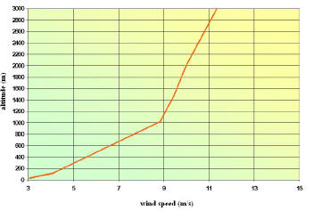
Fig. 1. Variation in the wind speed, as a function of the altitude, based
on the average European wind speed (3 m/s at ground level). Source: Delft
University, Dr. Wubbo Ockels
风速的变化,根据海拔高度的不同,以欧洲平均风速(地面为3M/S)为标准。来源:Delft
大学, Dr. Wubbo Ockels
with respect to 100 m (mean altitude at which the largest
wind mill operate) and, being all other parameters constant,
the generated power is eight times greater. Moreover, with
lines several hundred meters long, the airfoils can intercept
a wind front area much larger than the intercepted area of
wind mills, which for structural limits cannot go beyond the
size intercepted by 90 m rotor diameters of big 5 MW towers
(at present suitable only for off-shore installations, see [4]).
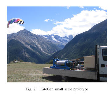
As a first step, in the KiteGen project a small scale prototype
has been realized (see Fig. 2) to show the capability of
controlling the flight of a single kite, by pulling the two lines
which hold it, in such a way to extract a significant amount
of energy. In this paper we investigate such a capability
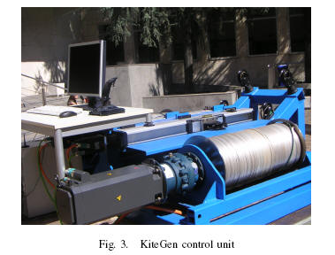
in simulation, employing the kite model used in [5]. The
overall maneuver is composed of two phases: the traction
and the recovery ones. The control unit (see Fig. 3) has two
electric actuators which act as motors in pulling the lines
for controlling the flight or for recovering the kite and as
generators if the lines length increases when pulled by the
kite. In the traction phase the control is designed such that
the kite pulls the lines, so that a certain amount of energy is
这种风力发电机的占地面积比同等发电量的风力场要少得多(约为50-100倍),且发电成本也少得多,后者约为前者的10-20倍。之所以有如此巨大的改进潜力,一方面是因为从风中得到的能量会随着每立方米的风速的增加而增加,另一方面也随着直吹向空地的风产生的能量而呈直线性上升。假设机翼能飞到几百米高,KITEGEN(风筝风力发电机)能利用自然事实,如随着海拔的增高,风力会增强且源源不断,见Fig.1.例,和100米高度相比,在800米的高空风速会加倍,成为参数的常量,其发电量会增大八倍。此外,由于风筝线几百米长风筝飞行器能拦截前方风力面积要比风车所能拦截的面积大得多,后者因为其结构上的局限,只能通国MW高塔直径90米的风轮拦截风流(目前仅适用于无支撑物的装置,见[4])。作为第一步(见Fig.2)风筝风力发电机项目中已完成小型模型的建造,来表明通过拉风筝上的两根线来控制其飞行的性能。这样来获取大量能量。该论文中,我们利用[5]中用的风筝模型来研究模型中性能。这个整体方案中含有两个阶段:牵引阶段和恢复阶段。控制组(见Fig.3)有两个致动器,可以作为发动机,通过拉风筝来控制风筝飞行状态或使风筝恢复原始状态;也可以作为发电机,条件是风筝拉动风筝线使之长度增加。在牵引阶段,设计控制器使风筝牵引风筝线以便产生一定数量的能量。
风筝风力发电机小型模型
generated. When the maximal length of the lines is reached,
the control enters into the recovery phase, where the kite
is driven to a region where the lines can be pulled by the
motors until the minimal length is reached, spending a small
fraction of the energy generated in the traction phase and a
new traction phase is undertaken.
当风筝飞到绳子的最大长度时,控制进入恢复阶段,风筝将被引向一特定区域,在这一区域发动机把绳子拉到其长度的最小限度,此时发电机只有一小部分处于牵引阶段,而新的牵引阶段则在酝酿之中。
The control design is here carried on using a Fast implementation
of a Predictive Controller (FMPC) as proposed
in [6] and [7]. Indeed, the design is formulated as an
optimization problem (power maximization in the traction
phase and minimization in the recovery phase) with state
and input constraints, since for example the kite height on
the ground cannot be negative and lines pulling and its rate
of variation cannot exceed given limits. From this point of
view, Model Predictive Control (MPC) appears to be an
appropriate technique. However, a “fast” implementation is
needed, in order to allow the real time control at the required
sampling time (of the order of 0.1 s). It can be noted that
MPC technique has been employed in [5] for kite control.
However, in [5], the concern was not on energy generation,
but the aim was to stabilize a given unstable periodic orbit
that can be obtained for constant line length. In this paper,
in order to investigate the energy extraction, the line length
is not supposed to be constant and no kite trajectory is
preassigned to be tracked. The derived kite trajectory is on
the contrary determined by the optimization of the generated
energy.
控制设计这儿用来使用快速感应控制器FMPC,如[6]和[7]中所提。确实,此设计也是做为一个解决问题的最优方案(产生的能量在牵引阶段达到最大值,在恢复阶段达到最低额)。比如说,风筝离地的高度是不能否定的,绳的长度也是一定的。从这一点看,感应控制模型MPC还是可行的。然而,快速感应也是必需的,以保证真实条件下的时间控制在所需时间范围内,约为0.1S。我们也能看出,MPC技术已被用于风筝控制,见[5]。然而,[5]所侧重的并非是能量的输出,而在于固定绳子原本不稳定的绕行周期,此周期因为绳子长度变化而变化。在本论文中,为了调查产能的多少,绳子的长度并未确定,风筝的轨迹也未做考虑。相反所得出的风筝轨迹则根据最佳产能量来定。
The paper is organized as follows. In Section II the used
kite model is presented. In Section III the MPC setup is
formulated and the control specifications are introduced; in
Section IV the used technique for the fast control implementation
is briefly described. The simulation results related to
the realized small scale prototype are presented in Section
V. Some conclusions and future developments are reported
in Section VI.
本论文内容安排如下:第二章节(Section II )
提出使用的风筝模型,第章节(Section III )用公式阐述MPC装置
,介绍控制器的技术要求,第四章节(Section IV)简要描述快速感应控制器的使用技术,第五章节(Section V)介绍小型模型的模拟结果。第六章节(Section VI)得出结论,展望未来发展。
II. KITE MODEL
二、风筝模型
The model originally developed in [5] is employed to
describe the kite dynamics. A fixed cartesian coordinate
system (X; Y;Z) is considered, with X axis aligned with
the nominal wind speed vector direction. Wind speed vector
is represented as ~Wl = ~W0 + ~Wt, where ~W0 is the nominal
wind, supposed to be known and expressed in (X; Y;Z) as:
最初[5]中所示的模型是用来解释风筝动力学的。用一个笛卡尔坐标系来说明,X轴表示额定风速向量,风速向量用此公式表示:~Wl = ~W0 + ~Wt,其中~W0指额定风速,用~W0 = Ã (Wx 00)(1)表示。
Wx(Z) is a known function which gives the wind nominal
speed at a certain altitude Z. The term ~Wt may have
components in all directions and is not supposed to be
known, accounting for wind unmeasured turbulence.
A spherical coordinate system is also considered, centered
where the kite lines are constrained to the ground. In this
system, the kite position is given by its distance r from the
origin and by the two angles µ and Á, as depicted in Fig. 4,
which also shows the three basis vectors eµ, eÁ and er of
a local coordinate system. These basis vectors are expressed
in the fixed cartesian system (X; Y;Z) by:
Wx(Z)是一个已知函数,赋予额定风速一个特定海拔Z,参数~Wt在各个方向都能延伸,可能是未知的,用以标明不稳定的干扰因素。
也可以用一个球形坐标系来解释。以风筝线系在地面的固定点为球心。在这一轴中风筝的位置由它到原点的距离r和 µ、 Á两个角度确定,如Fig.4所描述,Fig.4中还体现了一个局部坐标系三个基本向量eµ, eÁ 和 er。这些基本向量可由一固定坐标表示表示:
球形(立体)和局部坐标系
Applying Newton’s laws of motion in the local coordinate
system, the following equations are obtained:
where m is the kite mass. The external forces Fµ, FÁ
and Fr include the contributions of gravitational force mg,
aerodynamic force ~Faer and force Fc exerted by the kite on
the lines. Their relations, expressed in the local coordinates,
are given by:
其中m是指风筝质量。外力Fµ, FÁ和 Fr,包括重力mg,空气动力~Faer,风筝对绳的牵引力Fc。它们之间的关系在局部坐标系中可下列公式表示
(Fµ = sin (µ)mg + FaerµFÁ = FaerÁFr = ¡cos (µ)mg + Faerr ¡ Fc) (4)
where forces are assumed positive in the direction of basis
vectors eµ, eÁ and er.
~Faer depends on the effective wind speed ~We, which in the
local system is computed as:
力和方向可以肯定地根据基本向量eµ, eÁ and e的方向确定,~Faer随有效风速而定,在局部坐标系中可由下列公式计算得出:
(~We = ~Wa ¡ ~Wl) (5)
~Wa 是风筝的速度,在局部坐标系中可表示为:
(~Wa =0@µ_rÁ_r sin µr_1A) (6)
Let us consider now the kite wind coordinate system, with
the origin in the kite center of gravity, ~xw basis vector
aligned with the effective wind speed vector, ~zw basis vector
contained by the kite longitudinal mirror symmetry plane and
pointing from the top surface of the kite to the bottom, and
wind ~yw basis vector completing the right handed system.
In the wind coordinate system the aerodynamic force ~Faer
w is
given by:

再建一个风筝风位坐标系,以风筝的重心为原点,基本向量~xw和风速向量都在横轴上,基本向量~zw包含在风筝的纵向平面对称图中,此图涵盖了风筝的顶部到底部所有表面。~yw基本向量在右手坐标系。在此风位坐标系中,空气动力可由下式得出:
(~Faer w = FD~xw + FL~zw )(7)
其中FD是拉力,FL是起重力,可做如下计算:
(FD = ¡12CDA½jWej2FL = ¡12CLA½jWej2)(8)
其中½指空气密度,A为风筝特定面积,CL 和 CD分别是起重系数和拖拉系数。所有这些变量都是持续变化的。在局部坐标系中~Faer是一个多变非线性函数。
(~Faer =0@ Faer µ (µ;) Faer Á (µ; Á;) Faer r (µ; Á; r; Ã;)1A)(9)
(9)中所示的角度Ã是支配变量,可由下式定义:
(Ã = arcsinµ¢l d ¶ )(10)

在d是固定风筝的两条线之间的距离,¢l为两条线的长度差。角度Ã通过改变向量~Faer的方向来影响风筝的运动。
因为风筝只能对绳施加正力,力Fc就是那样的力。此外,Fc是通过驱动的自身控制来测量的,其控制方式为r_(t) ¼ r_ref(t),选择相对应的r_ref(t)。其结果为Fc(t) = Fc(µ; Á; r; _ µ; _ Á; _ r; _ rref; ~We)。其力的公式为P = r_Fc。在牵引阶段,选择r_ref(t) > 0,产生正力,风筝离地越来越远,致动器就作为作为发电机。在恢复阶段,要求选择r_ref(t) < 0,因为绳子会越来越短:产生了反作用力,由作为发动机的致动器做为动力源。
此时系统动力可如下所示:
(_ x(t) = g(x(t); u(t);Wx(t); _ rref(t); ~Wt(t))) (11)
where x(t) = [µ(t) Á(t) r(t) _ µ(t) _Á(t) r_(t)]T and u(t) =Ã(t).
其中,模型的所有情况都会有记录,作为控制情况的反馈。
III.用模型预测控制器控制风筝
本节主要讲述控制问题及其相关内容。第一节简介中突出的一点,也是主要问题即通过适当的对风筝的控制产生能量。为了达到这一目的,我们定义了一个由两个阶段构成的循环。这两个阶段分别为牵引阶段和恢复阶段。为了保证整个循环可以持续进行,第一阶段产生的能源总量要比第二阶段中所消耗的能源总量大,在开始另一循环之前,风筝必须有足够的能量恢复原状。两个阶段中,MPC控制器根据它们的自身功能,状况,输入能量限制及终止条件而设计。
对控制的运动的估算是在离散时间中进行的,这一时间是在所选的适当取样期¢t的基础上定义出来的。在每一取样期tk = k¢t, k 2 Z+,获取的数值x(tk)和风速Wx(tk), 以及所选的参考风速值都用以估算控制的运动, 这要通过该形式表现指数的优化来完成:
(J(U; tk; Tp) = Z tk+TptkL(x~(¿ ); u~(¿ );Wx(¿ ); r_ref(¿ ))d¿)(12)
其中Tp = Np¢t; Np 2 Z+是预计基准线(范围),x~( r)是根据 方程式(11)预测范围之内的预测状态,Wt(t) = 0, ~x(tk) = x(tk),
分段常量控制输入~u (t) 属于数列U = f~u(t)g; t 2 [tk; tk+Tp ],
定义为: (~u (t) = ½ ¹ui; 8t 2 [ti; ti+1] k + Tc; : : : ; k + Tp ¡ 1) (13)
其中Tc = Nc¢t; Nc 2 Z+; Nc ・ Np是控制范围。
以后将会讨论的是, 以风筝位于的操作阶段中达到的成果为基础 ,合适
地定义(12)中的函数L(.)。另外, 为了考虑风筝运动和不同阶段的控制输入Ã上的
物理限制,也已包含了数学式F ~x(t) + G~u(t) ・ H 。
因此,利用后退范围的方式计算出 预测控制定律 :
1)时间定量tk,得到x(tk)
2)解决最优化问题:
min
U
J(U; tk; Tp) (14a)
对应于
_~
x(t) = g(x~(t); u~(t);Wx(t); r_ref(t)) (14b)
F ~x(t) + G~u(t) ・ H; 8t 2 [tk; tk+Tp ] (14c)
3)应用解决最优化问题的数列U的第一元素到实际控制活动中
u(tk) = ~u(tk)
4)在下次抽样时间tk+1时重复整个程序
因此,预测控制器结果成了系统状态X,虚拟测算的风速WX和参数r_ref 的非线性静态函数:
Ã(tk) = f(x(tk);Wx(tk); r_ref(tk)) (15)
A 牵引阶段
该阶段的目的是从风流中尽可能多地获得机械能。下面最初状态值域,据认为是牵引阶段的开始:
µI ・ µ(t) ・ µI
jÁ(t)j ・ ÁI
rI ・ r(t) ・ rI (16)
其中
0 < µI < µI < ¼=2
0 < ÁI < ¼=2 (17)
大体地说,牵引阶段是当风筝在关于X坐标轴的均衡区域里开始的,高度是Z1 (rI cos µI ・ ZI ・ rI cos µI ).当
该阶段开始时,r_ref的有效值 r 被设置,以便风筝飞行时,r 的值增加,那时在线上用牵引力Fc, 因此产生 机械能,选定 r的值取得以下两者之间的折中,它们是获得牵引力值和风筝线上风速值。基本上来讲,风越强,能被设置获得力值r 的值就越高。牵引阶段的目标是使在值域[tk; tk + TP ] 产生
的能量最大,此时满足关于状态和输入值的限制。在每一瞬间得到的机械能是P = r_Fc,因此
选定下面的成本消耗值使在MPC设计(14)中达到最小:
J(tk) = ¡Z tk+Tp tk (r_(¿ )Fc(¿ ))d¿ (18)
在整个阶段,下面的状态限制被认为是保持风筝足够的远离地面:
µ(t) <・ µ (19)
其中 ,µ < ¼=2.致动器
物理限制决定这种限制:
jÃ(t)j ・ Ã
j _Ã(t)j ・ _Ã (20)
为了完成牵引阶段的描述,不得不介绍一下最后的情况。每根风筝线最初被缠绕在一个滑轮上,当风筝远离时就会展开。当 r 达到某一值-r 时,有必要将风筝线拉回来,以便使风筝风力发电机开始新的一轮工作,因此,达到下面的情况时,牵引力做功阶段结束,恢复阶段就能开始:
r(t) =- r (21)
B 恢复阶段
在该阶段,必须用最少的能量将风筝线扯回来,以便使整个循环纯获得能量最大化。恢复阶段被分为三个子阶段。
第一子阶段中,r_ref(t) 从-r 减至0,该控制操作的目的是在某一区域内移动风筝,其中 ⊙ 值小 ,/0/ 的值大,有效风速-We和牵引力Fc较小,用低能耗将风筝恢复到原始位置。下面分别介绍一下正值-OII 和⊙的值⊙II来认识该阶段。
数学式 (22)
一旦
达到下面的情况,jÁ(t)j ¸ Á II µ(t) ・ µII 数学式 (23)
第一恢复子阶段就完成了。
当第二恢复子阶段开始时,r_ref(t) 从 0 减至定值 -r,该值使风的反速度和低值Fc之间达到一种折中状态。
在该阶段,控制性操作的目的是使用在抵消风对风筝线的反作用上的能量最小。因此消耗的作用功函数是:
数学式 (25)
这意味着 ,r 可能达到最初牵引力做功状态值。然后第三个恢复子阶段就开始了,r_ref(t) 从负值r-. 增至0。控制的目的是使风筝位于牵引阶段开始的位置,如(16)描述的那样。作用功J(tk) 如下:
数学式 (26)
其中µ1 = (µI + µI )/2。 恢复阶段 最后结束 时的状态和牵引阶段的开始状态相同。
在整个恢复阶段,控制感应器问题考虑到(19)表述的状态限制和(20)表述的输入限制。
IV 快速预测控制感应
对以前描述的预测控制感应器来讲,控制参数Ã(tk) 结果
成为(15)表示的非线性固定函数,其可被重写作 Ã(tk) = f(w(tk))
其中w(tk) = (x(tk);Wx(tk); r_ref(tk))T . 对给出的w(tk) 而言,函数f(w(tk)) 的值可通过每次抽样时间 t k 时解决限制性最优化问题(14)而计算出来。然而,每次抽样时间的最优化问题在0.1秒时是难以解决的。
例如:[5]中显示的预测控制感应器之平均计算时间结果是一个工作台上大约0.45秒,这是在更简化的条件下对相同的风筝模型进行飞行控制。解决该难题的一种途径是在线外估算出f(w) 一定
数量的值,用来找出f 的一个近似值,使之用来作线上感应操作。
为更明确一点,设定一个限定值域 W C R8 其中 W 可变。
从一系列值Wv={ wk 2 W; k = 1; : : : ; º } 开始的MPC程序,以便:
Ãk = f( ~ wk); k = 1; : : : ; º 数学式 (27)
该项的目的是从Ãk 和~ wk 的已知值和f 的已知属性中得出f的近似值~f,并测出近似值误差。由于该近似值,中枢网络已应用于[8]中。与中枢网络有关的难题是:学术阶段中的局部最小化问题和处理勾画函数图像中处理限制因素遇到的问题。另外,并不提供近似值误差的测算。为解决这些问题,[6]已因涉及线性模型的公式而提出一种Set Membership 方法。基于这种方法,为测算近似值的误差而采用各种方式,f( ~ wk); k = 1; : : : ; v 有关的知识就不足够了,而需要关于f 的额外信息。该论文假设f Fr,其中Fr是一系列关于W的所有Lipschitz函数
,定量r.注意,由于在线性力学和二次方程函数的简单情况下f 都是一个分段线性持续函数[9],故不能进一步做出假使。运用在近似值的额外信息是输入饱和条件,jf(w)j ・ ¹ Ã. 这些关于函数f 的信息与在点wk 2 W; k = 1; : : : ; V 时
函数值的知识结合起来能得出f2 FFS ,其中系列 FFS (可行性函数系列),定义为:
数学式 (28)
概括了f 的有关整体信息。根据Lp(W) 标准p 属于[ 1,∞],利用上述整体信息允许得出f 的最大化估算值及其近似值误差,被定义为:
//f//p约等于(数学式)。已给出f=f.相类的Lp近似值误差是。该误差不能被确切地计算出来,但最小范围已给出:
数学式 (29)
其中E()被叫做(保证)近似值误差,函数f*被叫做最优化近似值,其条件是 E(f*)=,定量rp叫作信息范围,保证Lp 近似值误差,让我们定义:
数学式 (30)
结果函数:(31)是任何? 的一最优化近似值,其中?
另外,*的近似值误差被分段界定为:?
极限是:(32)
因此,估算?,可能的是决定选定的r是否是以达到估算f中要求的精确度,或者?是否不得不被增加。
能够得出r的估算值?,如下
数学式(33)
该估算值
的 极限是r :
数学式(34)
注意,极限结果(32)和(34)成立,条件是?,其中? 是定量W和W 之间的Hausdorff 距离
,例如 如果通过W的恒定值?得出W?
因此,MPC 控制就能近似地在线上完成,这要通过每次抽样时间简单估算函数?
增加V,近似值误差就减小,而计算时间就会增加。在下面显示的数字情形下,在所有操作情况下,在用V=10000计算?中,小于1%。在dSpaceRMicroAutobox(800MHz clock) 上执行的控制步骤计算要求的相应平均时间大约是0.01秒,极大地低于要求的抽样时间。
V 模拟成果
这里介绍一下三种模拟的成果。表I 显示模型和控制参数的值,表II 中含有识别每个阶段开始和结果情况的设定值,以及设定和输入限制的值。
由于风筝线以0.5米每秒的速度伸展180米,牵引阶段持续大约360秒,在恢复阶段风筝线缠回的速度是-2.3米每秒,因此第二个恢复子阶段持续80秒,最小风速如(1):
数学式(35)
0米高度时最小风速是4米每秒,100米时增至6米每秒,300米时增至7.7米每秒。在第一次模拟中,认为没有风的干扰,因此,W()=0?。在第二次模拟中沿着Y坐标轴纵向风干扰Wt, y(t)如下:
数学式 (36)
其中 W0=2?。最后,在第三次模拟中,下面沿着z坐标轴的侧向风干扰W?如下:
数学式(37)
(37)中描述的干扰含有2个侧向风阶段:在牵引阶段第一个持续100秒,第二个应用于整个恢复阶段。注意,wt,y 和Wt,z的振幅等同于100米高度最小风速的50%和20%,因此给该系统引入了很复杂的因素。
图像5 显示风筝在风速最小化情况下的运动轨迹。图像6描绘风筝在牵引阶段风筝的一些运动轨迹,可以看出,该阶段风筝轨迹像个”躺着的8“,时间大约为5秒,因此,仅一牵引阶段中就完成大约75次轨迹。该循环中产生的能量如图像7:平均值是1.58KW,而每圈733kJ
在图像8中,显示产生能量系数(36)描述的横向风力的干扰:完成这一循环生产的能量值727KJ,几乎和没有干扰时获得的能量一样,表明控制系统对纵向风力干扰的很好忍耐力。
有(37)描述纵向风力干扰存在情况下,模拟产生的能量的情形如图9所示:风力第一阶段造成产生能力值较低(618KJ),而该循环都能完成,显示出强烈纵向风力存在下该系统很强的抗干扰能力。
图5 虚拟情况下的风筝轨迹
图6 一些牵引阶段的轨迹
VI 结论和未来发展
本论文已进行首次研究旨在调查控制涡轮飞行物的性能,以便设计出新性的风力发电机,使之能弥补现有风能发电技术的主要缺陷,获得的结果令人鼓舞,但这是基于风筝上的模拟状态,当然其只能给出相关的力学的近似描述。的确,精确模模仿无翼飞行器动态是一项相当有挑战性的任务,希望基于这种模型的控制设计可能不在所建的模型上以一种理想方式进行。因此,识别诸如[10],[11]复杂的非线性系统的改进方法计划应用于从该模型中获得的测算,以便获得更精确的模型,使之足以从NMPC 设计中得到较好的效果。该模型已被组建好,目前正在测试期。(如图像2和3)
图8 一次循环中生成的无干扰情况下和有干扰情况下产生的能量,横向风干扰
必须提到的是目前论文中报道的结果是关于专为已组建的模型设计的小型风筝(5平方米的特定面积)。在风筝面积50平方米,风速40米每秒的模拟状态下产生的能量是200KW,产生相同能量的一只风筝高40米,重约62吨,耗用约900.000,00牛顿的力。风筝风力发电机重量和耗用力的期望值分别为8吨和60.000,00牛顿,尽管这些值仅部分被证实,但也证明利用控制性飞行器发电的潜力之大。将进行研究更有效的构造以实现首次模型的成功运行,其提供的潜力更大。在此构造中,飞行器和转轴相连接(如图片10)设计的控制器使飞行器传到转轴臂上的能量最大,适合与发电机相连。根据我们初步的估算,此类风力发电机比现有的风田发电机所耗的电能生产成本低得多(高达10-20倍),其能产生高达250MW每平方千米的电能,而风田发电只是3MW每平方千米。
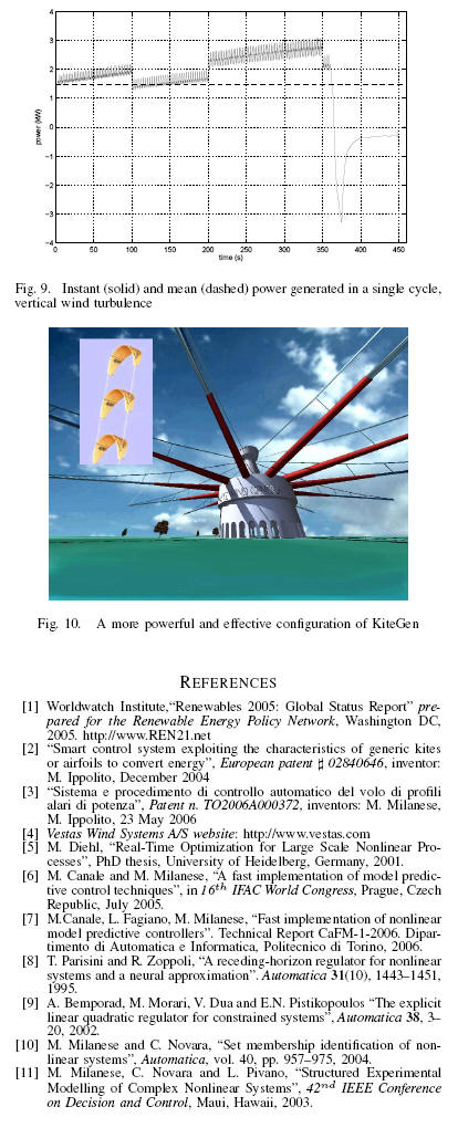
图10 一种更强更有效的风筝风力发电机构造
参考文献
Supported by Regione Piemonte under the Project “Controllo di aquiloni
di potenza per la generazione eolica di energia” and by Ministero
dell’Università e della Ricerca of Italy, under the National Project “Robustness
and optimization techniques for high performances control systems”.
M. Canale, L. Fagiano and M. Milanese are with Dipartimento di
Automatica e Informatica, Politecnico di Torino, Italy. M. Ippolito is with
Sequoia Automation, Italy
e-mail: massimo.canale@polito.it, lorenzo.fagiano@polito.it,
m.ippolito@sequoiaonline.com, mario.milanese@polito.it